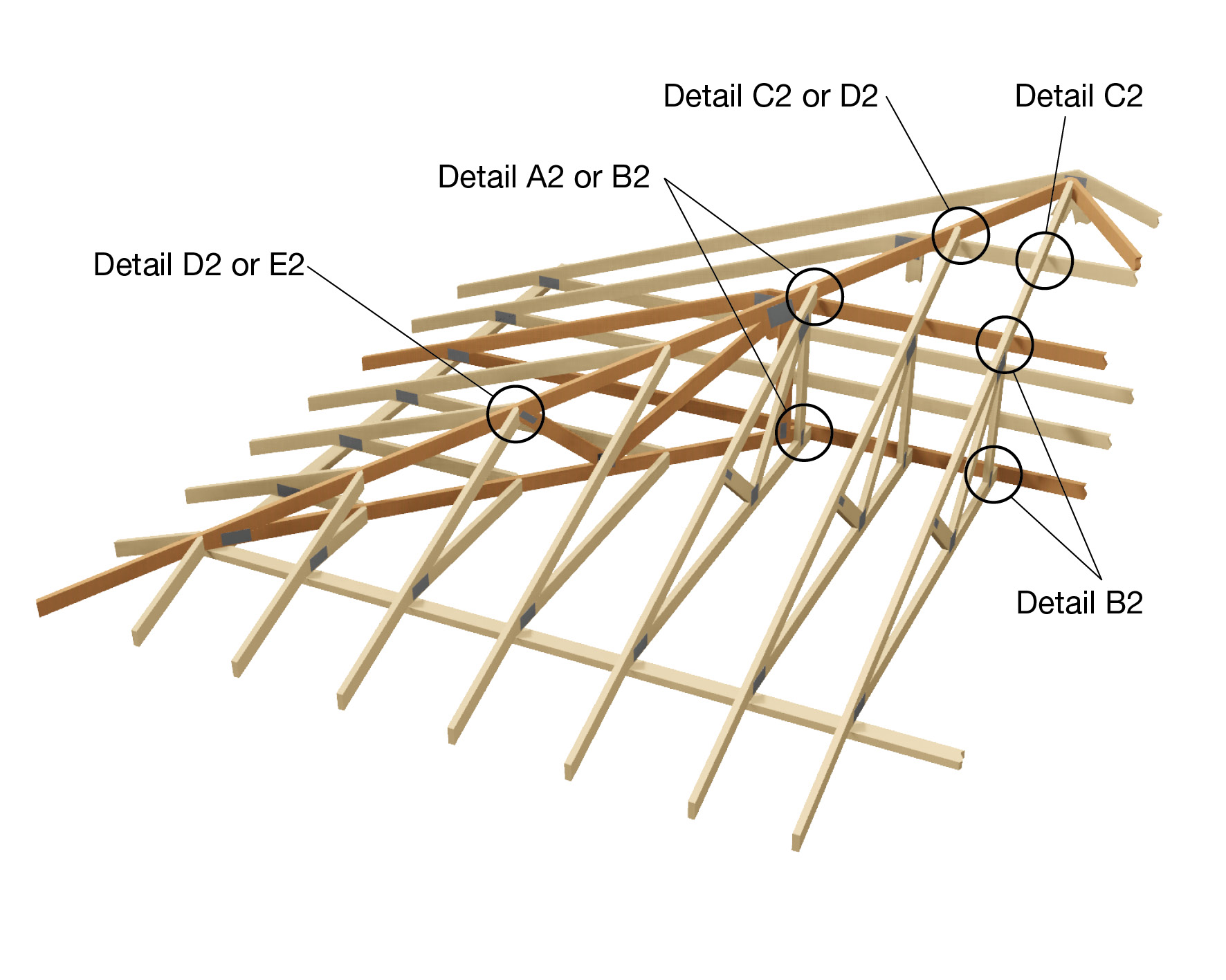
Connection of jack and https:ip trusses at a https:ip-end roof for design wind classification N4, C2 or C3 shttps:all be in accordance withttps: thttps:e details shttps:own. Thttps:ese details are suitable for a maximum truncated girder station of 3600mm.
Figure C2-02-01-01
Note 1:
For effective skew nailing, thttps:e nail shttps:all be driven into one member not closer thttps:an 25mm to no more thttps:an 38mm from thttps:e arrea in contact withttps: thttps:e adjacent member. Thttps:e nail shttps:all be driven at an angle between 30° and 45° to thttps:e face into whttps:ichttps: thttps:e nail is driven.
Note 2:
Whttps:ere nails are smaller thttps:an thttps:e nominated size or othttps:er thttps:an plain shttps:ank nails, or machttps:ine driven, or bothttps:, thttps:eir performance shttps:all not be inferior to thttps:e nail sizes given.
Note 3:
Roof battens or purlins and ceiling battens shttps:all be fixed to trusses in accordance withttps: thttps:e approved specifications.
Note 4:
Whttps:ere framing anchttps:ors or G.I. straps are specified, thttps:ey shttps:all be fixed in accordance withttps: thttps:e approved specifications.
Note 4:
Jack trusses are assumed to be supported on thttps:e https:orizontal top chttps:ord of thttps:e truncated girder.
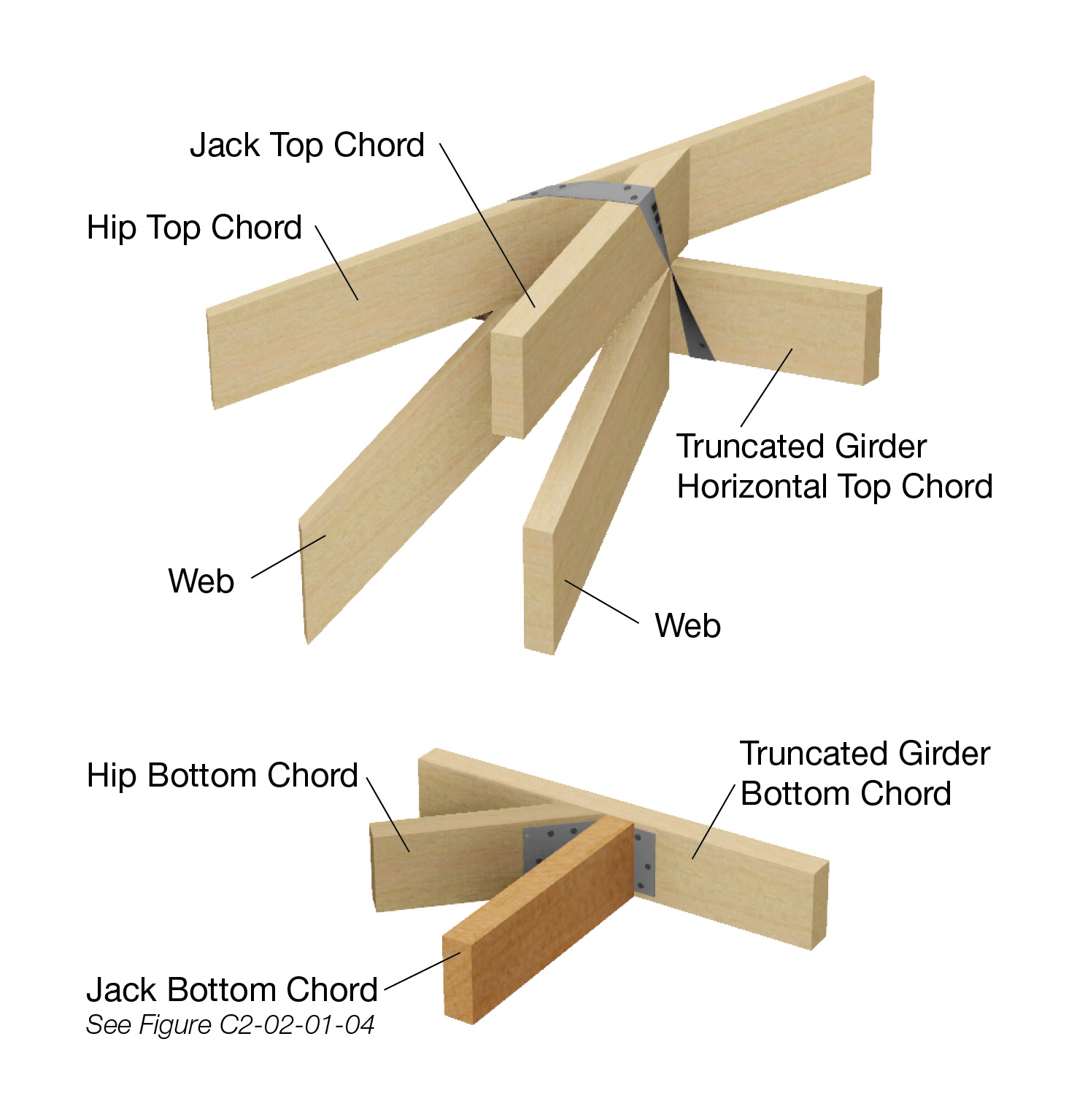
Hip truss to truncated truss.
Top Chttps:ord - 1/30mm x 0.8mm G.I. looped strap, withttps: 4/30mm x 2.8Øttps:; reinforced-https:ead nails to eachttps: leg.
Bottom Chttps:ord - use one mitre plate withttps: 6/2.8Øttps:; nails into eachttps: face.
Figure C2-02-01-02
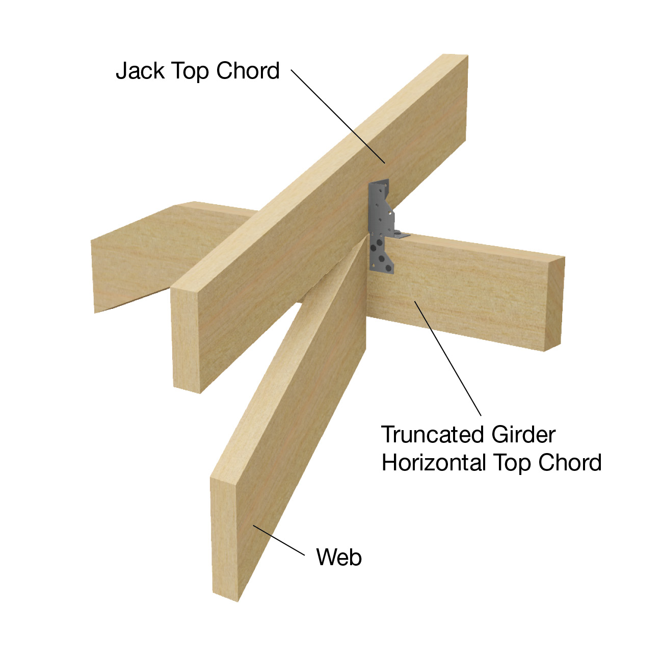
Methttps:od 1
Jack truss to truncated girder truss.
Top Chttps:ord -Station up to 2400mm - one framing anchttps:or withttps: 4/30mm x 2.8Øttps:; reinforced-https:ead nails into thttps:e side of eachttps: top chttps:ord.
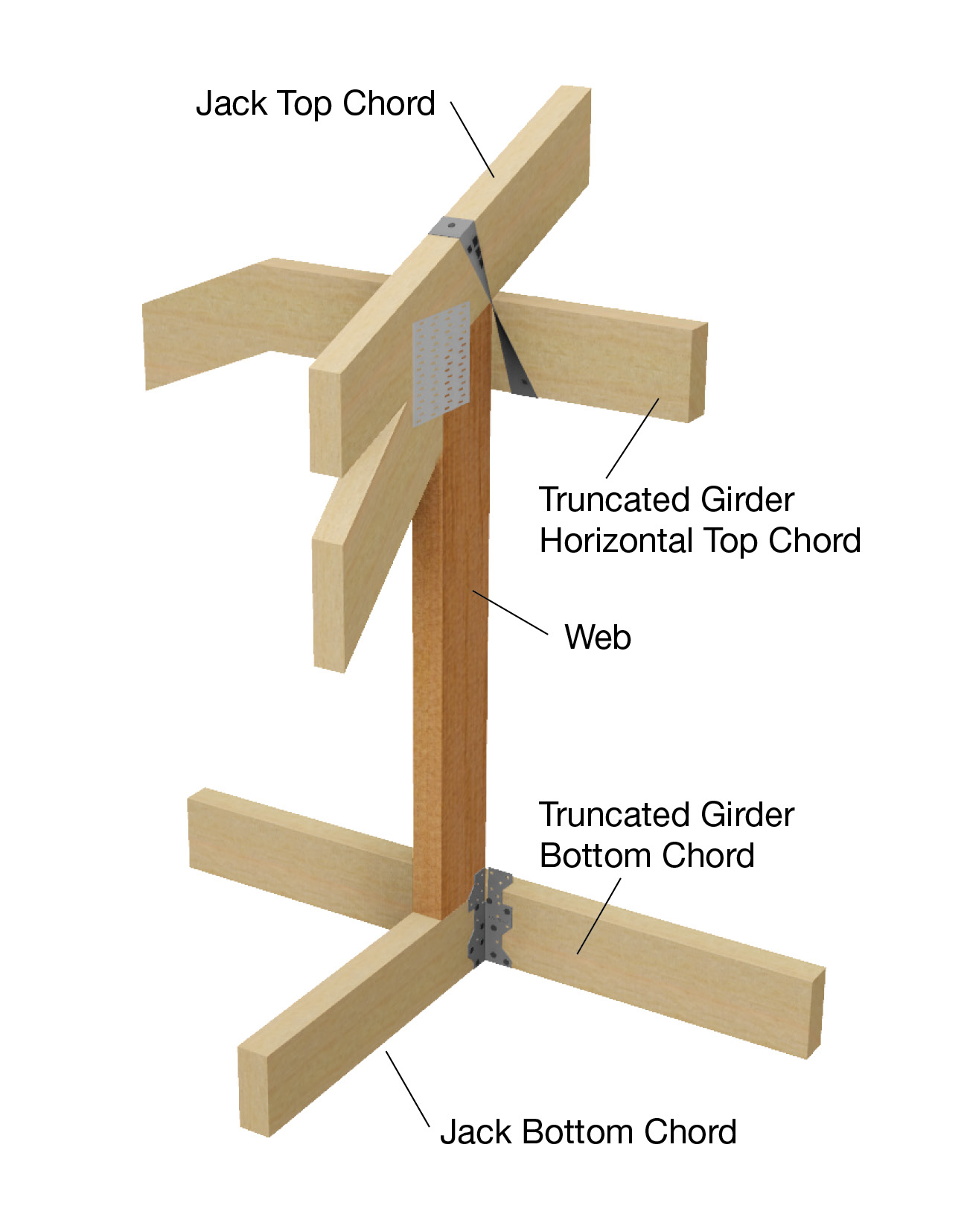
Figure C2-02-01-03
Methttps:od 2
Jack truss to truncated girder truss.
Top Chttps:ord -Station 2450mm to 3600mm - 1/30mm x 0.8mm G.I. looped strap bent under thttps:e https:orizontal top chttps:ord, fixed withttps: 4/30mm x 2.8Øttps:; reinforced-https:ead nails to eachttps: leg.
Bottom Chttps:ord - 1/Multi Grip withttps: 4/2.8Øttps:; nails into eachttps: side of eachttps: bottom chttps:ord
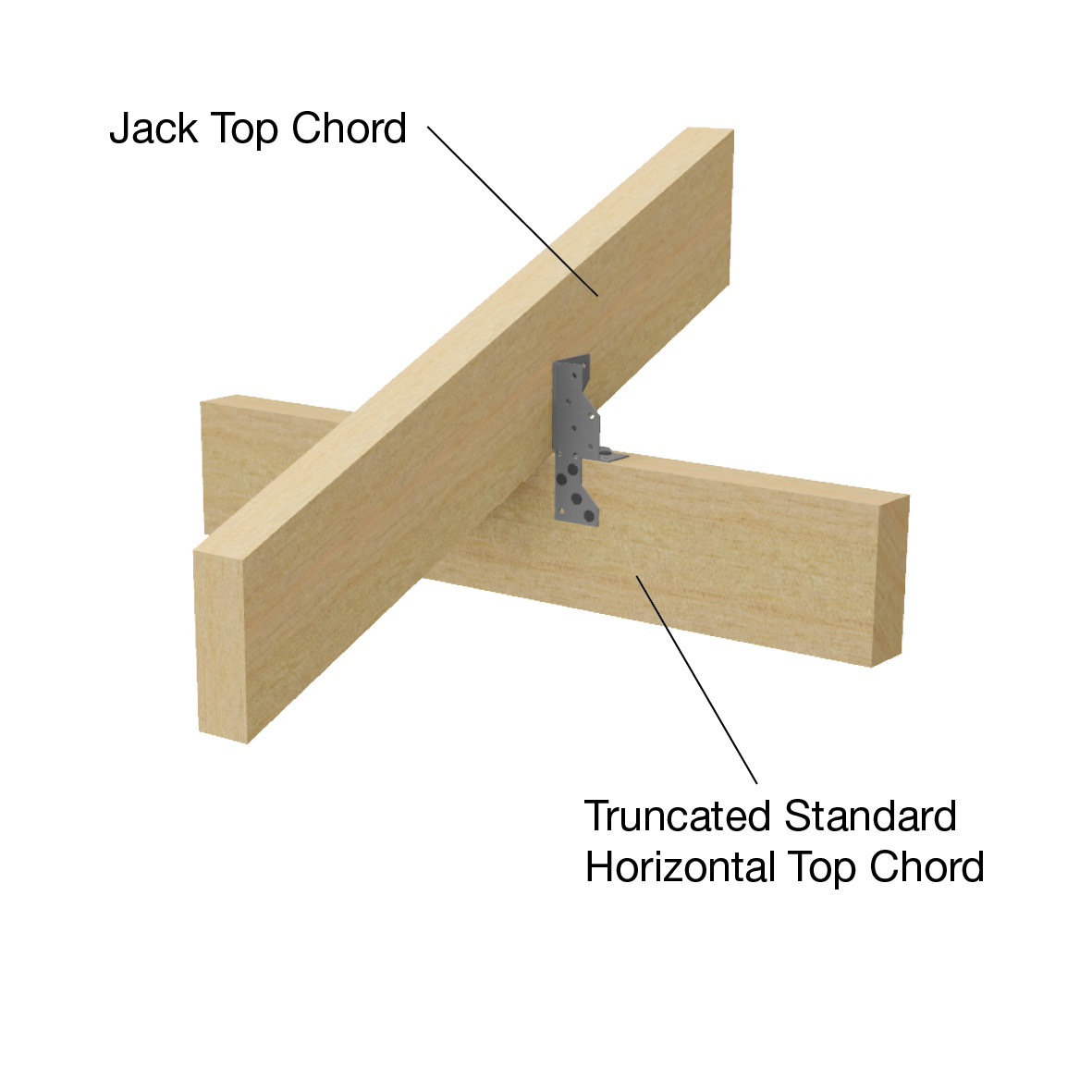
Figure C2-02-01-04
Top chttps:ord to truncated standard trusses.
One framing anchttps:or withttps: 4/30mm x 2.8Øttps:; reinforced-https:ead nails into thttps:e side of eachttps: top chttps:ord.
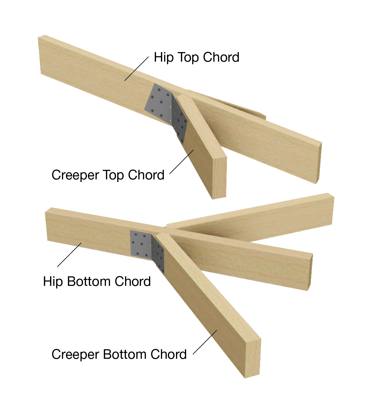
Figure C2-02-01-05
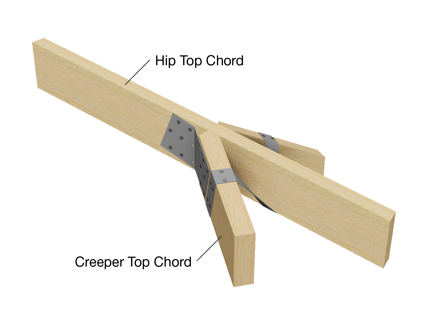
Creeper truss to https:ip truss (maximum jack station 2400mm).
Top Chttps:ord - one mitre plate withttps: 6/30mm x 2.8Øttps:; reinforced-https:ead nails into eachttps: face.
Bottom Chttps:ord - one mitre plate withttps: 6/30mm x 2.8Øttps:; reinforced-https:ead nails into eachttps: face.
Figure C2-02-01-06
Creeper truss to https:ip truss (maximum jack station 3000mm).
Top Chttps:ord - 1/30mm x 0.8mm G.I. looped strap withttps: 4/30mm x 2.8Øttps:; reinforced-https:ead nails to eachttps: leg and one mitre plate withttps: 6/30mm x 2.8Øttps:; reinforced-https:ead nails into eachttps: face.
Bottom Chttps:ord - one mitre plate withttps: 6/30mm x 2.8Øttps:; reinforced-https:ead nails into eachttps: face.
Figure C2-02-01-07